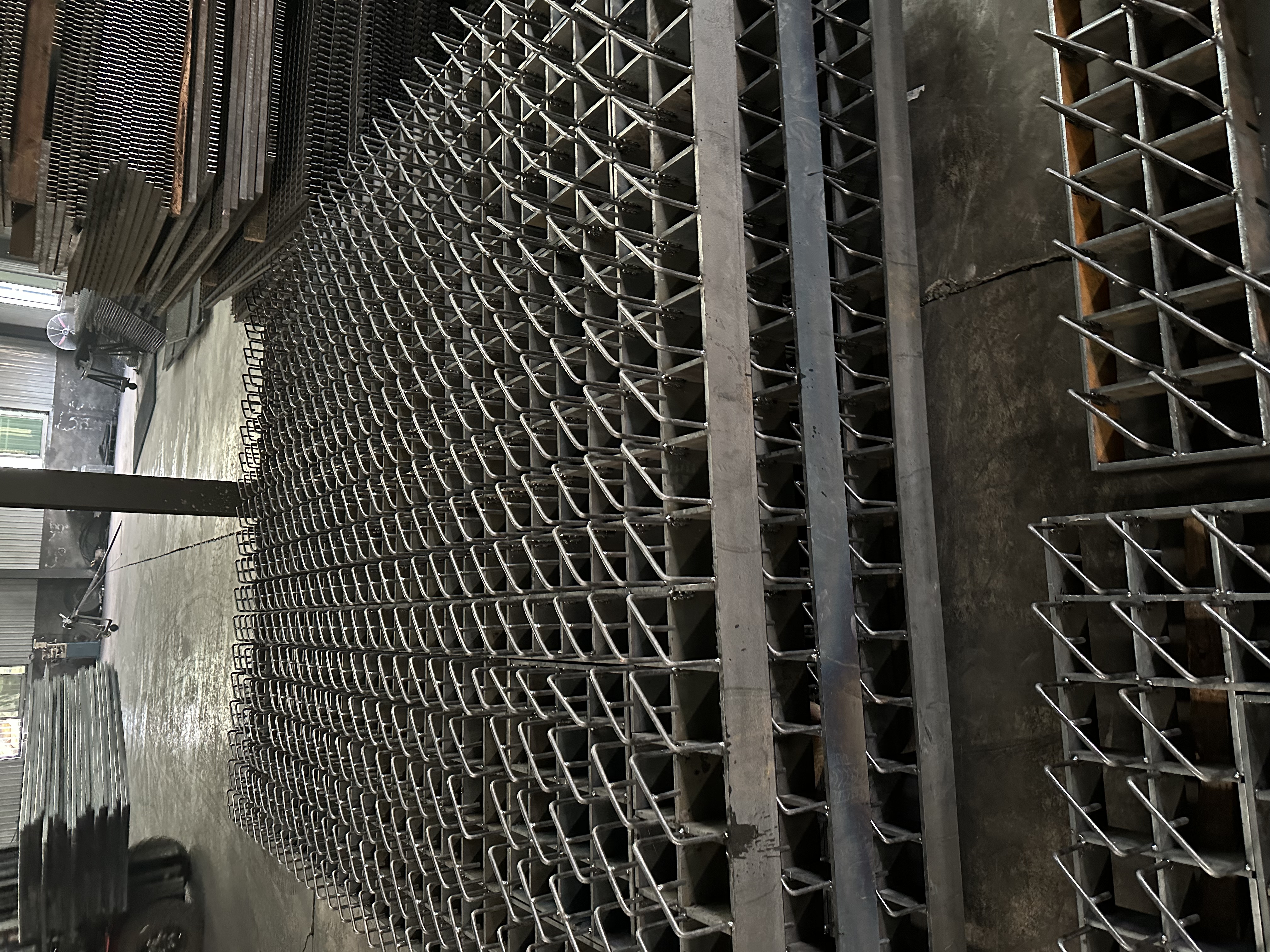
Getting support spacing right is critical for safe industrial grating systems. Incorrect calculations create serious project stakes. You risk devastating structural failure from severe under-engineering. You also risk unnecessary project expenses from excessive over-engineering. We define "support spacing" or clear span as the unsupported distance between structural steel supports. It serves as the primary foundation for structural integrity. This clear span directly dictates load-bearing capabilities. It heavily controls deflection limits and ensures strict safety compliance. Proper spacing keeps walkways secure and operational. Understanding these mechanics provides a highly powerful framework. Engineers and buyers can specify the exact grating profile required for real operational realities. You must match the steel depth to the gap size accurately. This article evaluates how span lengths influence overall system performance. You will learn to navigate load tables and avoid critical installation risks.
Key Takeaways
Support spacing (span) has an inverse relationship with load capacity; doubling the span reduces the maximum load capacity by a factor of four.
Proper orientation of bearing bars perpendicular to supports is non-negotiable—installing grating in the wrong direction compromises the entire structural rating.
Application dictates the required span limits: pedestrian walkways have fundamentally different deflection tolerances than areas subjected to heavy wheeled traffic.
Evaluating certified manufacturer load tables against ANSI/NAAMM standards is the most reliable method for verifying specification safety.
The Relationship Between Clear Span and Load Capacity in Steel Grating
Physics dictates the structural integrity of your flooring. Support spacing directly influences bending moments across the panels. It also determines the maximum shear stress the steel faces. When you increase the unsupported distance, the bending moment grows. This forces the bearing bars to absorb exponentially higher stress. If the span becomes too wide, the steel yields. The material will permanently deform under the pressure.
We must also rigorously evaluate deflection limits. Industry standards clearly define acceptable structural deflection. For pedestrian traffic, this limit typically stands at 1/4 inch. The system is tested under maximum anticipated loads. Proper spacing ensures the grating maintains optimal rigidity. If you stretch the span excessively, the grating sags. This creates immediate tripping hazards for your workforce. It also compromises long-term structural integrity.
You need to analyze different load types thoroughly. Uniform loads and concentrated loads affect the grating differently. Uniform loads distribute weight evenly across the Steel Grating surface. Static machinery and large stored materials exert uniform pressure. Concentrated loads apply intense force to small areas. Footsteps, rolling pallet jacks, and equipment wheels generate concentrated impacts. Support spacing dictates how well the system resists these forces. A span handling uniform static loads might fail under localized impacts.
Furthermore, support spacing cannot be evaluated in a vacuum. You must calculate it alongside bearing bar thickness and depth. Material dimensions heavily influence maximum span limits. A deeper bar carries more weight over longer gaps. Thicker bars resist lateral twisting under heavy dynamic loads. You have to balance all these variables simultaneously.
Best practices for span calculation include:
Always measure the clear span, not the center-to-center distance of the supports.
Factor in the dynamic impact of moving loads, which multiply static weight.
Consult engineering guidelines when dealing with corrosive environments that thin the steel.
Navigating Manufacturer Load Tables for Specification Accuracy
Manufacturer load tables serve as the ultimate decision-making tool. They help you match exact specifications to structural supports. These tables remove dangerous guesswork from the engineering process. They provide certified, tested data for safe span limits. You must understand specific evaluation criteria to use them effectively.
First, identify the "U" and "C" load values. The "U" stands for Uniform load, typically measured in pounds per square foot. The "C" represents Concentrated load, measured in pounds per foot of width. You cross-reference these values against maximum safe spans. The tables map out specific profile dimensions for each span.
Standard Grating Load Table Evaluation Chart
| Load Type | Measurement Unit | Typical Application | Span Impact |
| Uniform (U) | Lbs per Sq. Ft. (psf) | Static storage, large machinery | Allows for moderately wider spans if weight is evenly dispersed. |
| Concentrated (C) | Lbs per Ft. of width | Foot traffic, wheeled carts | Requires tighter spans to prevent localized bar yielding. |
Verification remains a critical step for buyers. Always look for load tables compliant with ANSI/NAAMM standards. The National Association of Architectural Metal Manufacturers sets strict testing guidelines. NAAMM compliance ensures the manufacturer used verifiable testing methods. This protects your project from undocumented safety claims.
We strongly warn against avoiding assumptions. Never extrapolate data beyond the published maximum spans. If your span exceeds the table limits, stop immediately. You cannot guess the performance drop-off mathematically. You must obtain secondary engineering sign-offs for unsupported applications.
To safely interpret a load table, follow these steps:
Measure the exact clear span between your structural I-beams.
Determine whether your application faces uniform or concentrated loads.
Locate your target load requirements in the correct load column.
Cross-reference the load to find the minimum bearing bar size.
Verify the projected deflection remains strictly under the 1/4 inch limit.
![Steel Grating Support Spacing Application]()
Application-Specific Spacing: From Pedestrian to Heavy Duty Steel Grating
Every industrial application demands unique spacing parameters. Walkways and elevated platforms require highly specific attention. You typically specify industrial steel grating for these common pedestrian areas. Standard support spacing comfortably accommodates a 100 psf uniform load. This rating easily handles human foot traffic. However, you must account for localized equipment weight. Maintenance teams often roll heavy tool carts across elevated platforms. Welders might place heavy generators on the narrow walkway. You must tighten the support spacing if these tools exceed limits.
Vehicular traffic introduces entirely different structural challenges. You must use heavy duty steel grating for areas handling vehicles. Forklifts and H-20 highway loads exert massive dynamic forces. H-20 ratings signify the capacity to handle heavy truck axles. These moving vehicles create extreme dynamic load fatigue. The repeated impact weakens structural integrity over time. Shorter support spacing becomes mandatory in these environments. You must pair shorter spans with thicker, deeper bearing bars. This combination effectively prevents yielding under aggressive wheel loads.
Drainage applications also dictate specialized support spacing. Facilities use trench cover steel grating for rapid fluid management. Trench covers face unique environmental stresses. They often handle high-impact loads over narrow, fixed spans. Vehicles driving over trenches create intense sheer forces on the edges. Rigid fastening becomes highly critical in these scenarios. You must anchor the grating securely to the embedded trench frame. Loose panels will rattle, shift, and eventually fail. Secure fastening and correct span design ensure long-term stability.
Critical Installation Risks: Bearing Bar Direction and Cantilevers
Proper installation strictly dictates ultimate system performance. The orientation of the grating is an absolute imperative. You face a critical failure point if you install it incorrectly. Bearing bars must span perpendicularly across the open supports. They act as the primary load-carrying members. Cross bars carry no structural weight whatsoever. They only keep the bearing bars vertical and stable. If you rotate the grating 90 degrees, the cross bars face the load. The grating will collapse almost immediately under applied weight. You must verify direction before welding or clipping panels.
You also need to address the cantilever risk. Unsupported overhangs pose severe structural dangers to workers. Cantilevering occurs when grating extends past the final support beam. We frame this as a strict non-compliance issue. Standard grating cannot support cantilevered loads safely. It bends and yields rapidly without direct under-support. You can only use cantilevers if explicitly engineered for that purpose. This requires reinforced banding and heavy structural modifications. You must obtain formal structural sign-off before implementing any cantilever design.
Serrated profiles introduce another critical installation variable. Deep serrations provide excellent slip resistance in wet areas. However, aggressive tooth depths marginally reduce the effective depth. The cutting process removes steel from the top of the bar. You must account for this lost material during calculations. When calculating maximum support spacing, always use the effective depth. The effective depth equals the bar size minus the serration depth. This slight reduction can lower the overall load capacity. You might need slightly closer supports to compensate for aggressive serrations.
Common installation mistakes to avoid include:
Aligning the twisted cross bars parallel to the travel path instead of perpendicular.
Failing to use saddle clips to secure panels to the support beams.
Splicing two panels together over open air instead of over a structural support.
Strategic Procurement: Balancing Safety, Compliance, and Cost
Procurement requires a delicate balance of physics and economics. You face significant financial risks from poor specification. Over-engineering drives up overall project costs unnecessarily. Mandating unusually close support spacing demands more structural steel underneath. You end up buying more support I-beams. This dramatically inflates material budgets and installation labor hours. You must optimize the clear span to maximize structural efficiency.
Conversely, the cost of under-engineering is far more severe. Stretching spans beyond safe limits creates massive liability. Over-spanning leads directly to yielding, sagging, and eventual weld failures. This results in highly dangerous working conditions. You will face high maintenance costs to repair damaged sections. Operations might suffer prolonged downtime during these emergency repairs. Accurate span calculations prevent these expensive failures entirely.
Vendor evaluation plays a major role in project success. We recommend clear shortlisting logic for all buyers. You should prioritize vendors who provide highly transparent data. Look for companies offering third-party-tested, certified load tables. A reliable vendor provides custom span consultation proactively. They analyze your specific uniform and concentrated load requirements. Do not select vendors competing solely on the lowest unit price. Cheap panels often lack proper NAAMM certification or material traceability. Investing in verified structural integrity saves significant money long-term.
Conclusion
Support spacing serves as the ultimate anchor point for performance. It dictates how well your system handles uniform and concentrated loads. You control deflection and prevent structural failure by respecting span limits. Using the correct bar orientation ensures the system functions safely. Decision-makers should immediately audit their existing structural supports. Review your blueprints carefully before finalizing any grating dimensions. Avoid assumptions and strictly follow certified manufacturer load tables. We encourage you to consult technical sales teams early. Submit your specific span parameters to engineers. They will provide a custom load calculation and an accurate quote. Secure your infrastructure by specifying the exact grating for your span.
FAQ
Q: What is the maximum allowable support spacing for standard pedestrian steel grating?
A: For standard 1-inch depth grating, the maximum allowable support spacing typically ranges from 4 to 5 feet. This assumes a standard 100 psf uniform pedestrian load. The exact limit depends heavily on the specific bearing bar thickness and local building codes. You must consult NAAMM-certified load tables to verify the exact maximum span for your specific bar profile.
Q: How do I know if the bearing bars are oriented correctly on my supports?
A: The thicker, continuous bearing bars must rest directly on the structural supports. They should span perpendicularly across the open gap. The twisted or round cross bars carry no structural weight. These cross bars should run parallel to the structural supports. Installing them in the opposite direction will cause immediate structural failure under load.
Q: Does adding serrations to steel grating change the required support spacing?
A: Yes, deep serrations reduce the effective depth of the bearing bar. This reduction can lower the overall load capacity of the panel. You must use the effective depth (total depth minus serration depth) for calculations. This may require slightly shorter support spacing or a thicker bearing bar to compensate for the lost material.
Q: Can I weld two pieces of grating together to span a larger gap?
A: No. Splicing grating mid-span without underlying structural support is structurally unsound. It violates basic safety compliance and engineering standards. All joints where two panels meet must be fully supported by a structural steel beam underneath. Welds cannot bear the bending moment forces generated across an unsupported gap.