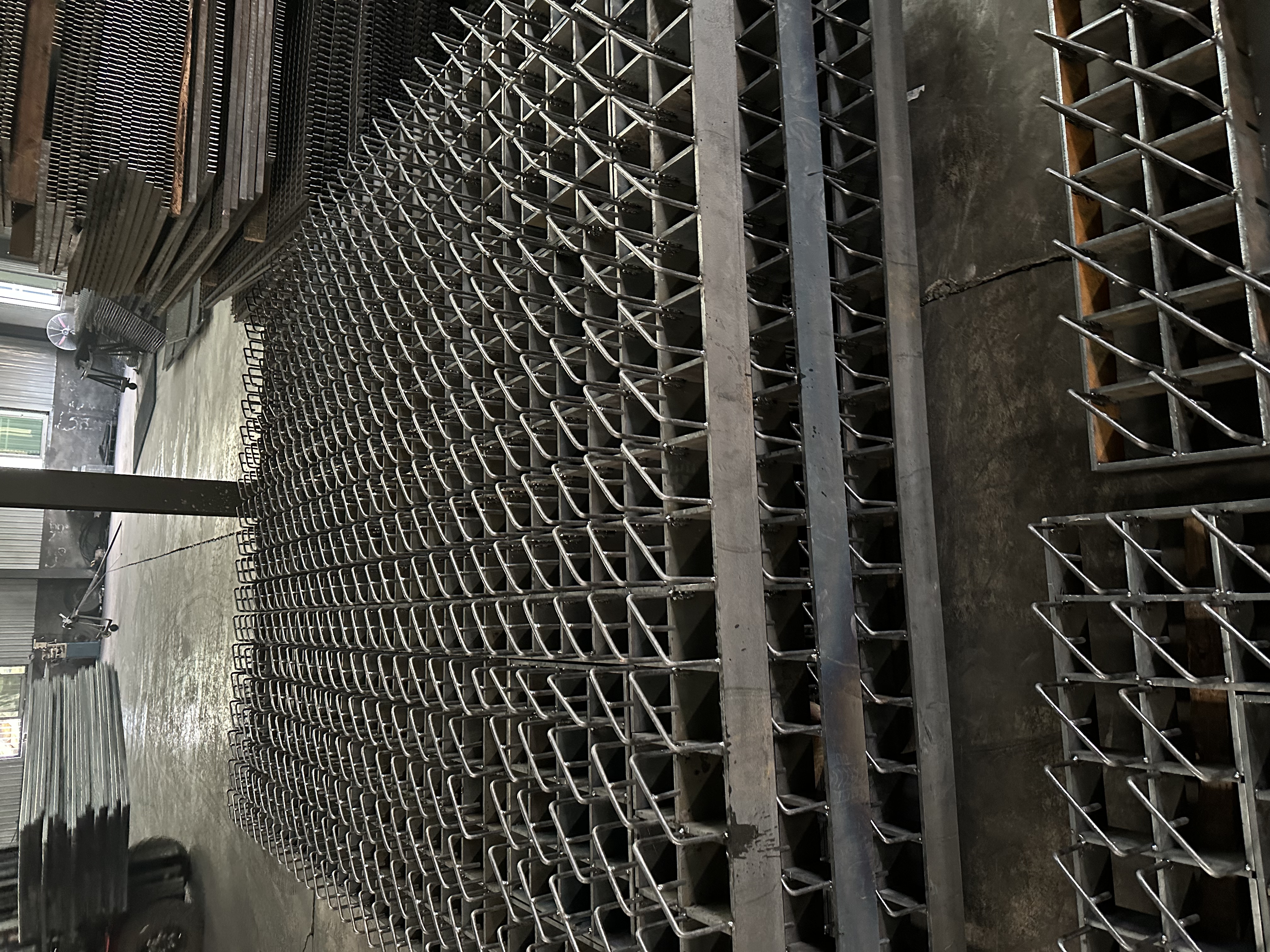
In structural engineering and facility management, specifying grating based solely on yield strength represents a critical error. We often see buyers focus entirely on how much weight steel can hold before breaking. They ignore how much the material bends. However, deflection is the true limiter for safety and longevity. Deflection refers to the degree to which a structural element displaces under a load. In industrial flooring, unchecked deflection compromises everything from pedestrian comfort to mechanical integrity. When a floor yields underfoot or beneath a heavy forklift, it creates immediate physical hazards. The purpose of this article is to provide a comprehensive decision-making framework for evaluating load tables. You will learn how to meet stringent safety compliance standards like those set by OSHA and NAAMM. We will guide you through selecting the exact grating specifications required to mitigate structural failures and operational risks entirely.
Key Takeaways
- Deflection limits dictate the maximum clear span of grating; exceeding standard limits (e.g., 1/4" for pedestrian traffic) compromises structural integrity and worker safety.
- Correctly interpreting manufacturer load tables requires distinguishing between uniform and concentrated loads across specific span distances.
- Material selection and bar depth matter, but improper installation (e.g., wrong bearing bar orientation) can immediately invalidate load capacities.
- Specifying Heavy Duty Steel Grating is mandatory for rolling vehicular loads, whereas standard industrial grating suffices for pedestrian zones.
The Hidden Costs of Poor Deflection Control (Business & Safety Risks)
Worker Safety & Ergonomics
Industrial platforms require absolute stability. When floors bounce, workers instinctively hesitate. This hesitation disrupts their natural walking gaits. Excessive yielding directly causes physical fatigue over long shifts. Legs work much harder on uneven, spongy surfaces. A bouncy floor feels inherently unsafe to anyone traversing it. It also creates micro-tripping hazards. Small vertical lips form between adjacent panels under differential loading. Tripping hazards increase significantly in fast-paced industrial zones. You cannot ignore the psychological toll on personnel. Workers slow down when they lose confidence in the floor. This directly impacts daily operational productivity. Facility managers must prioritize highly rigid walking surfaces. Proper deflection control guarantees a stable, confident footing.
Equipment Damage
High deflection ruins expensive material handling equipment. Rolling loads suffer immensely on yielding surfaces. Think about standard pallet jacks and heavy forklifts. They rely on smooth, continuous paths. When panels deflect, the wheels hit tiny dips repeatedly. Casters wear out prematurely due to these micro-impacts. Material handling becomes highly inefficient and extremely noisy. We often see axles bend unnecessarily from repeated shock loads. Equipment maintenance cycles shorten rapidly in these conditions. Bearings shatter when wheels strike the edges of deflected panels. You end up replacing wheels constantly. A rigid floor prevents this accelerated wear and tear. It keeps operations moving without mechanical interruptions.
Compliance & Liability
Deflection is a strict safety and compliance issue. You must meet established NAAMM MBG 534 standards. NAAMM stands for the National Association of Architectural Metal Manufacturers. Their standards act as a primary engineering baseline. Ignoring these standards invites massive workplace liability. A non-compliant floor exposes operators to severe lawsuits. Safety inspections look specifically for these structural flaws. OSHA inspectors recognize unsafe walking surfaces immediately. If someone trips due to excessive panel bowing, you face negligence claims. Proper deflection limits ensure both legal and physical protection. They provide a documented defense against structural failure allegations. You must engineer compliance into the floor from day one.
Uniform vs. Concentrated Loads
Load tables often confuse many procurement teams. Let us break them down clearly. You will always see the letters "U" and "C" in manufacturer charts. "U" stands for Uniform Load. It measures weight in pounds per square foot (psf). You use this metric for stationary loads or crowds of pedestrians. It assumes the weight spreads equally across the entire grating area. "C" stands for Concentrated Load. It measures weight in pounds per foot of grating width. You evaluate this metric for wheel loads or heavy machinery footings. A concentrated load applies intense pressure at the mid-span. The mid-span represents the weakest point of any panel.
Load Evaluation Comparison Matrix
| Load Type | Abbreviation | Measurement Unit | Primary Application | Critical Design Consideration |
| Uniform Load | U | lbs/sq ft (psf) | Pedestrian traffic, stored materials | Spreads weight evenly across the entire structural span. |
| Concentrated Load | C | lbs/ft of width | Vehicles, equipment, point loads | Applied directly at mid-span to test maximum stress. |
The 1/4-Inch Deflection Rule
Why do we talk about 1/4 inch? It serves as the universal industry benchmark. Pedestrians feel completely safe on rigid floors. If a floor bends more than a quarter of an inch, it feels unstable. Human senses detect even minor structural vibrations. A 1/4-inch limit ensures maximum physical comfort. It prevents structural fatigue across standard clear spans. Exceeding this limit causes the steel fibers to stretch repeatedly. Over time, this stretching induces permanent deformation. Permanent deformation means the panel will never return to flat. Adhering to the 1/4-inch rule preserves the grating indefinitely.
Safety Factors and Impact Multipliers
Engineers use highly transparent assumptions in load tables. They build standard charts around static loads. A static load does not move or drop. However, actual industrial environments feature highly dynamic elements. Rolling wheels create heavy, continuous impacts. Dropped tools generate sudden shockwaves. Engineers must apply dynamic impact factors when evaluating supplier data. You cannot rely blindly on raw load charts.
- Identify the base weight of the heaviest moving vehicle.
- Add the maximum weight of its loaded cargo.
- Multiply the total weight by a 1.2 or 1.5 impact factor.
- Check this new value against the concentrated load column.
This process guarantees long-term durability under real-world abuse.
![Industrial steel grating installation showing proper bearing bar depth]()
Matching Specifications to Application Requirements
Standard vs. Heavy Duty Applications
Not all flooring solutions are created equal. You must analyze the exact traffic type first. Pedestrian zones use standard specifications comfortably. However, vehicular traffic demands immediate structural upgrades. You must specify Heavy Duty Steel Grating for rolling loads. Think about H-20 truck ratings or massive forklift fleets. Forklift traffic requires significantly thicker bearing bars. They also need specialized bar spacing to prevent wheel trapping. Standard panels will crush instantly under a 10,000-pound forklift. Heavy-duty variants resist torsional twisting. They distribute concentrated wheel loads effectively across multiple support beams. You should never compromise on heavy-duty specs in high-traffic zones.
Environmental & Material Lenses
Harsh environments degrade raw steel remarkably quickly. Corrosive atmospheres destroy structural integrity without warning. Chemical plants and offshore rigs face relentless moisture. Rust literally eats away the bearing bar thickness. This loss of mass drastically increases deflection over time. A panel originally rated for 300 psf might hold only 100 psf after rusting. You need appropriate surface treatments immediately. Specifying Galvanized Steel Grating establishes a highly resilient baseline. The hot-dip galvanizing process bonds zinc to the steel perfectly. This zinc coating stops rust entirely. It acts as a sacrificial barrier against corrosive elements. It preserves the exact load-bearing capacity for decades. Galvanizing remains the most effective defense against rust-induced deflection.
Span-to-Depth Ratio Framework
How do you choose the right bar depth? You must use a span-to-depth framework. The clear span directly dictates the required bar depth. Longer spans inherently need deeper bearing bars. This physical reality maintains acceptable deflection limits. A one-inch bar might cross a two-foot span safely. It will fail miserably across a four-foot span.
- Measure the exact clear span distance between your structural supports.
- Determine whether the primary traffic is pedestrian or vehicular.
- Identify the absolute maximum expected dynamic load.
- Consult the manufacturer table for the minimum required depth.
- Verify the calculated deflection stays strictly under 1/4 inch.
The Fatal Implementation Flaw: Bearing Bar Orientation
Installation Realities
Proper engineering cannot fix terrible installation practices. We see one common field error constantly. Unskilled contractors install the grating sideways. They let the thin cross bars bear the structural load. This happens because square panels look identical from afar. Cross bars merely connect the bearing bars together. They keep the main bars upright and stable. Cross bars offer zero independent structural support. They cannot hold weight across an open span.
Structural Consequence
Incorrect span direction invites absolute disaster. It reduces the designed load capacity to near zero. You will see immediate, severe deflection under minimal weight. This simple orientation error often leads to catastrophic failure. People get seriously hurt when platforms collapse unexpectedly. A panel rated for thousands of pounds fails under a single person. The cross bars snap, and the bearing bars twist horizontally. The entire floor gives way instantly. You must treat orientation as a critical life-safety parameter.
Risk Mitigation Strategies
You can prevent these fatal errors early. Control the procurement and planning phases strictly. Specify clearly banded edges on all open ends. Banding helps installers orient the panels correctly by visual inspection. It provides a solid border perpendicular to the bearing bars. You should also provide crystal-clear installation schematics.
- Specify end banding requirements during the initial quote phase.
- Request detailed layout drawings from the manufacturer.
- Paint bright directional arrows on panels before shipping them.
- Train site contractors on basic visual identification techniques.
- Conduct a pre-installation walkthrough to verify support layouts.
Never leave orientation up to guesswork. Ensure every contractor understands the load-bearing direction.
How to Shortlist and Vet Grating Suppliers
Tolerance and Testing
You must ask manufacturers hard questions upfront. Ask them directly, "Do your tables account for NAAMM manufacturing tolerances?" Real-world manufacturing creates minor dimensional variances. Steel bows slightly during the cooling process. High-quality suppliers test their panels rigorously to account for this. They control dimensional tolerances tightly in their facilities. They factor these slight imperfections into their published load tables. Cheap suppliers publish theoretical data based on perfect, impossible conditions. You need real-world testing data to ensure safety. Look for suppliers who maintain active quality assurance departments.
Custom Fabrication Capabilities
Avoid field cutting whenever physically possible. Evaluate suppliers on their extensive custom fabrication skills. They should provide precise factory cuts based on your drawings. They must band all edges around pipe penetrations properly. They need to band intricate cutouts around structural columns. Factory banding maintains local structural integrity perfectly. It prevents localized deflection spikes where bearing bars were severed. Field-cut panels without banding weaken the floor drastically. A good supplier handles all complex geometry in-house before shipping.
Documentation Requirements
Demand hard proof before buying anything. Ask for complete engineering submittals for every project. Request official material test reports (MTRs) for the steel used. Insist on verified, stamped load tables. Do this before ever issuing a purchase order. Thorough documentation prevents dangerous surprises later during site inspections. It proves the steel matches the required yield strength. It confirms the manufacturer stands behind their deflection calculations. Keep these documents permanently for compliance audits.
Conclusion
Proper deflection calculation remains absolutely non-negotiable. It guarantees safe, rigid industrial platforms for everyone. It ensures strict regulatory compliance across your entire facility. Controlling deflection delivers durable, long-lasting flooring solutions that require minimal maintenance. You protect your workers from fatigue and your equipment from premature wear.
You must stop guessing using generic charts found online. The stakes are simply too high in industrial settings. We strongly encourage you to consult an in-house engineering team today. Review your site-specific spans and load requirements carefully. Request a custom technical consultation to verify your assumptions. Ask a reputable manufacturer for a detailed, engineered quote based on exact deflection limits.
FAQ
Q: What is the maximum allowable deflection for pedestrian steel grating?
A: Typically 1/4 inch under a uniform load of 100 psf, per NAAMM standards. This specific limit ensures pedestrians do not feel a "bounce" or instability while walking across the platform. Exceeding this threshold compromises both structural safety and daily worker comfort.
Q: Does galvanizing affect the deflection or strength of steel grating?
A: No. The hot-dip galvanizing process adds a protective zinc coating for excellent corrosion resistance but does not alter the underlying steel's structural deflection properties. It merely preserves the initial engineered strength by preventing future rust-induced material degradation.
Q: Why is my steel grating bowing under rolling loads?
A: It is likely specified for static pedestrian loads instead of dynamic rolling loads. This specific issue indicates an immediate need to switch to heavy-duty specifications. You must apply appropriate dynamic impact factors to account for the continuous stress of heavy wheels.
Q: Can I increase the span of my grating by rotating it?
A: Absolutely not. Bearing bars must always run perpendicular to the structural supports. Rotating the grating shifts the heavy load directly to the smaller connecting cross bars. This severe installation mistake leads to immediate, catastrophic failure and extreme safety hazards.