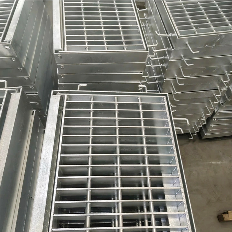
Industrial platforms demand reliable foundations, but stability goes beyond choosing thick metal. Often overlooked, the spaces between structural bars dictate safety and performance under pressure. Incorrect cross bar spacing compromises lateral rigidity. This subtle flaw leads directly to premature deflection, safety hazards, and failed compliance under dynamic loads. Facility managers frequently miss this detail. They focus solely on main load-bearing components. Consequently, poor spacing decisions trigger dangerous panel twisting and structural fatigue over time.
Selecting a optimal spacing configuration demands a strict balance. We must weigh load distribution, material weight, open-area needs, and project budgets carefully without over-engineering the solution. This guide breaks down the structural mechanics of cross bar intervals. We provide a technical framework to specify correct dimensions for industrial, commercial, and high-traffic platforms. You will learn how precise spatial distribution prevents buckling, supports heavy machinery, and maintains critical safety standards across varied environments.
Key Takeaways
- Cross bars function primarily to stabilize bearing bars; reducing spacing from standard (e.g., 4") to close-mesh (e.g., 2") significantly increases lateral stability.
- Tightening cross bar spacing increases overall steel grating weight and cost, necessitating precise alignment with application load requirements (pedestrian vs. vehicular).
- Specialized environments (e.g., pharmaceutical cleanrooms, heavy-duty transit) dictate specific spacing to balance debris fall-through, sanitation, and point-load resistance.
- Integrating specific profiles—such as welded serrated finishes or insert structures—requires matching cross bar frequency to maximize traction and structural integrity.
The Structural Mechanics of Cross Bars in Steel Grating
The Anatomy of Stability
Understanding platform integrity starts with identifying component roles. Bearing bars carry the primary vertical load. They run parallel to each other and span the structural supports. Cross bars serve an entirely different but equally vital function. They prevent lateral buckling and dangerous twisting, also known as torsion. When heavy objects rest on a Steel Grating surface, compressive forces push down. Without cross bars holding them perfectly vertical, bearing bars would simply fold over under this pressure. Cross bars lock the main load-bearing elements into a rigid grid. They transfer lateral stresses across the entire panel seamlessly.
Deflection Limits
Panel bending behavior changes drastically based on cross bar intervals. We call this the deflection curve. Point loads concentrate massive downward force on a very small area. Tighter cross bar spacing distributes this acute stress across multiple neighboring bearing bars. This rapid distribution flattens the deflection curve significantly. The surface remains rigid under heavy footfalls or equipment drops. Uniform loads also benefit deeply from this rigidity. A stiffer panel provides a much safer walking surface for workers carrying heavy materials. It eliminates the trampoline effect often felt on under-specified catwalks.
The Weight vs. Rigidity Trade-Off
Engineers must acknowledge a fundamental physical constraint. Decreasing spacing directly increases the dead weight of the grating panel. Adding more cross bars requires substantially more raw material. Consequently, panel weight spikes. You cannot add rigidity without adding mass. The supporting structures below the platform must then safely carry this extra dead weight. Stronger beams and reinforced columns become necessary. Designers must constantly calculate whether the gained surface rigidity justifies the heavier, more robust support framework required underneath.
![Steel grating spacing applications]()
Standard vs. Close-Mesh Spacing: Evaluation Framework
Selecting the right spacing directly impacts both safety and facility operations. We generally categorize spacing into two main groups. Standard and close-mesh configurations serve vastly different operational needs. Knowing when to deploy each prevents catastrophic failures and overspending.
Standard Spacing Profile
Industry norms typically set standard spacing at 4 inches or roughly 100mm. This configuration suits the vast majority of general industrial applications. It works perfectly for standard industrial catwalks and everyday pedestrian traffic. Wide intervals provide maximum ventilation and excellent light passage. Open layouts allow rain, snow, and large debris to clear the walking surface easily.
However, limitations certainly exist here. These panels remain susceptible to minor lateral sway. Heavy, localized dynamic loads can induce slight but noticeable vibrations. They do not handle repetitive rolling loads well over long periods.
Close-Mesh Spacing Profile
Close-mesh spacing tightens the interval to 2 inches or roughly 50mm. This dense configuration excels in high-vibration environments. It proves essential for public spaces requiring strict ADA compliance. Planners often combine tight cross bars with closely spaced bearing bars. This stops wheelchairs, canes, and high heels from catching in the grid. It acts as an excellent solution for heavy-impact drop zones near heavy machinery.
We must consider the limitations before specifying them. Close-mesh designs carry a noticeably higher procurement cost. The dense grid restricts the passage of larger debris chunks. This blockage quickly becomes a major negative in high-spillage industrial environments like mining or paper mills.
Comparative Evaluation Chart
| Spacing Type | Typical Interval | Ideal Environment | Primary Advantage | Main Limitation |
| Standard | 4" (100mm) | Catwalks, walkways | High open area, lightweight | Susceptible to point-load sway |
| Close-Mesh | 2" (50mm) | ADA spaces, drop zones | Maximum lateral rigidity | Restricts debris, higher cost |
| Custom Ultra-Tight | 1" (25mm) | Cleanrooms, specialized transit | Blocks almost all dropped items | Highest weight and unit cost |
Application-Specific Spacing Requirements
Different industries subject platforms to radically different stresses. A one-size-fits-all approach routinely fails. We must match the structural grid to the exact environmental hazards present.
- Vehicular Traffic & Heavy Loads: Rolling loads demand much closer cross bar spacing. Forklifts, pallet jacks, and trucks generate intense kinetic energy. Tighter cross bars distribute this rolling energy efficiently across the panel. They prevent dangerous weld-shear failures. Wide spacing simply cannot handle repetitive wheel impacts safely. The metal fatigues rapidly. Wheels exert severe twisting forces on the bearing bars. Close spacing locks those bars down, neutralizing the twisting action before welds crack.
- Pharmaceutical & Sanitary Environments: Sanitation protocols dictate strict spatial limits. Evaluators look closely at cleaning accessibility. Wide spacing prevents contamination pooling. It allows thorough, rapid washdowns. Too many cross intersections trap harmful bacteria and chemical residue. Planners must balance structural needs carefully against rigorous hygiene demands. A cleanroom cannot afford hidden crevices where microbes multiply.
- Elevated Walkways & Trench Covers: Dropped tools present extreme dangers on elevated platforms. Tighter spacing catches falling wrenches, bolts, and hardware. You protect vulnerable workers operating below. Conversely, trench covers need specific open-area ratios for rapid drainage. We balance fluid flow against heavy load support capabilities. A trench cover must stop trucks from falling in while letting floodwaters pass through instantly.
Evaluating Spacing in Specialized Grating Profiles
Managing Slip Resistance and Friction
Specialized surface finishes require matching cross bar intervals to function properly. Welded Serrated Steel Grating provides excellent grip for workers. The frequency of cross bars interacts deeply with these serrated bearing edges. You need continuous, unyielding slip resistance. Frequent cross bars enhance structural stiffness in highly wet or oily environments. They keep the jagged bearing edges perfectly aligned underfoot. If spacing drifts too wide, the bearing bars flex slightly when stepped on. This minute flexing reduces shoe traction dramatically. The worker's boot loses firm contact with the serrated teeth, increasing slipping risks.
Mechanical Locking Pressures
Different manufacturing techniques change how panels achieve stability. Insert Platform Steel Grating relies purely on mechanical locking rather than heat welding. Analyzing spacing becomes incredibly critical here. Locked or press-inserted platform gratings need precise spatial distribution to hold together. Tighter cross bar intervals lock the entire structure down securely. The friction fit relies on consistent pressure. If intervals stretch too far apart, the mechanical friction fit weakens. The platform can lose integrity over time under heavy vibrations. Precision spacing ensures the inserted bars never rattle or shake loose.
Common Specification Risks and Implementation Realities
Engineering platforms involves navigating numerous practical traps. Avoiding these common mistakes saves significant time and resources during installation and daily operations.
- Under-Specifying for Cost Reduction: Choosing standard spacing for dynamic load applications is highly dangerous. Buyers sometimes do this to cut initial procurement budgets. Heavy forklift traffic destroys under-specified panels very quickly. Hidden risks emerge rapidly as panels warp permanently. You face constant, disruptive replacement cycles. These specification errors drain maintenance budgets rapidly.
- Mismatched Tolerances: Incorrect spacing ruins field-cutting operations. Installers struggle to band cut panels properly on site. Structural integrity drops sharply if a field cut lands too far from a supporting cross bar. The exposed bearing bars lose their lateral support. Precise tolerances ensure smooth, secure installations. Poor planning forces messy, weak field modifications that compromise safety.
- Corrosion and Weld Integrity: More cross bars mean more intersection points. Every welded joint acts as a potential vulnerability. Highly corrosive environments attack these specific joints relentlessly. You must ensure proper galvanization reaches every corner. If protective zinc coatings fail to penetrate tight intersections, rust accelerates rapidly. We always weigh the necessity of extra stabilizing bars against chemical exposure risks.
Common Mistakes Matrix
| Specification Mistake | Immediate Consequence | Operational Impact |
| Using 4" spacing for forklifts | Weld shear and bar twisting | Platform failure, equipment damage |
| Ignoring field cut tolerances | Unbanded, weak panel edges | Tripping hazards, difficult installation |
| Over-specifying in corrosive zones | Too many weld nodes trapping acid | Accelerated localized rusting |
Conclusion
Base your final specifications strictly on a verified manufacturer load table. Match the cross bar interval to the heaviest anticipated point load your facility will experience. Always verify the required open-area percentage for your specific environmental conditions. Balancing rigidity against drainage needs remains the core challenge in platform design.
Advise your engineers and procurement buyers to request standard dimensional tolerances early. Review detailed CAD drawings for your specific spans before authorizing production. Consult directly with the manufacturer regarding custom spacing viability. Taking these proactive steps ensures your structural platforms remain secure, compliant, and highly durable for decades.
FAQ
Q: Does closer cross bar spacing increase the load-bearing capacity of steel grating?
A: No, bearing bars primarily dictate actual weight capacity. Cross bars simply provide lateral stability. They prevent the main load-bearing bars from buckling or twisting under pressure. Reducing their interval stiffens the panel but does not change the core maximum vertical load limits.
Q: What is the standard cross bar spacing for general industrial platforms?
A: The industry standard sits at 4 inches or 100mm. This dimension perfectly suits general pedestrian walkways, basic catwalks, and light storage areas. It allows excellent light penetration and keeps manufacturing complexity relatively low.
Q: How does cross bar spacing affect grating pricing?
A: Closer intervals require more raw material per square foot. They also demand significantly more welding or mechanical locking time. These factors combined increase production effort, raising final unit costs compared to standard wider layouts.
Q: Can cross bar spacing be customized for existing structural spans?
A: Manufacturers can adjust configurations, but strict limits exist. Automated welding machines operate on set indexing intervals. Custom spacing might disrupt standard panel widths, complicating field installation. Always verify machinery capabilities with your supplier before specifying highly unusual dimensions.